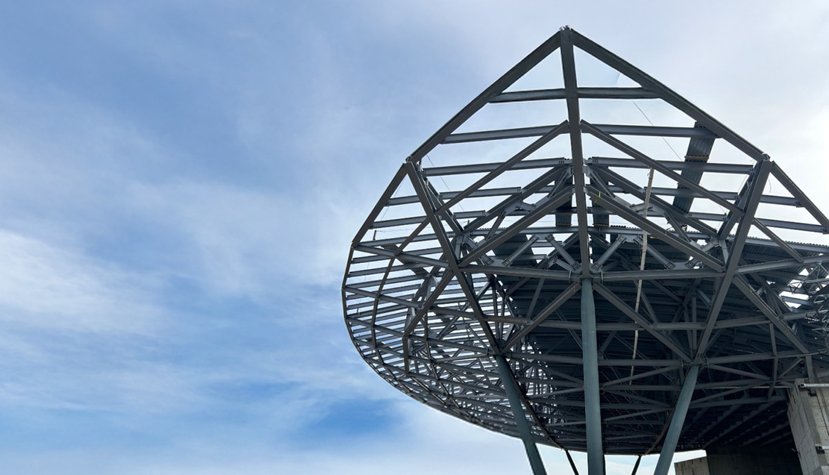
Platform on concrete and steel in construction

With the intuitive and user-friendly drafting software Parabuild, drawing detailed steel structures in 3D is easy and fast for any user, even the less practiced draftsman. From this 3D model, the software automatically generates quality shop drawings, bills of materials and DXF and DSTV files for production control. The software ensures that more automation and thus efficiency gains on the shop floor are not lost in the drawing room. Rudy Joris of Parabuild updates us on two major new functionalities in the software that result in even more efficient production: 3D welding and layout marking.

Parabuild's software focuses on drawing detailed steel structures in 3D as efficiently as possible. "It is the only steel structure drawing program that allows you to draw steel structures completely defined by geometric rules," says Joris. "Joints and macros defined in template drawings can be reused in any project to automate repetitive work. This includes whole structures, trusses, wind bracing, cladding, stairs, ... This means it is possible to customize Parabuild without hiring a programmer or writing complicated code."

Parabuild has a library of hundreds of standard steel building connections. "Drawing connections is a matter of selecting the steel profiles and the software suggests only the valid types in that situation," Joris explains. "The connection is drawn immediately and any changes are immediately displayed on the 3D model. Drawing a fully detailed steel structure is easier than ever."


The 3D model of the steel structure is used as the basis to automatically generate shop drawings, parts lists, CNC and IFC files. Outline plans, approval plans, etc. are easily created and connected to the 3D model. Bematings and designations are automatically added to shop drawings, and advanced optimization algorithms ensure proper placement so that shop drawings are clear and legible. This automation results in correct drawings and avoids errors.


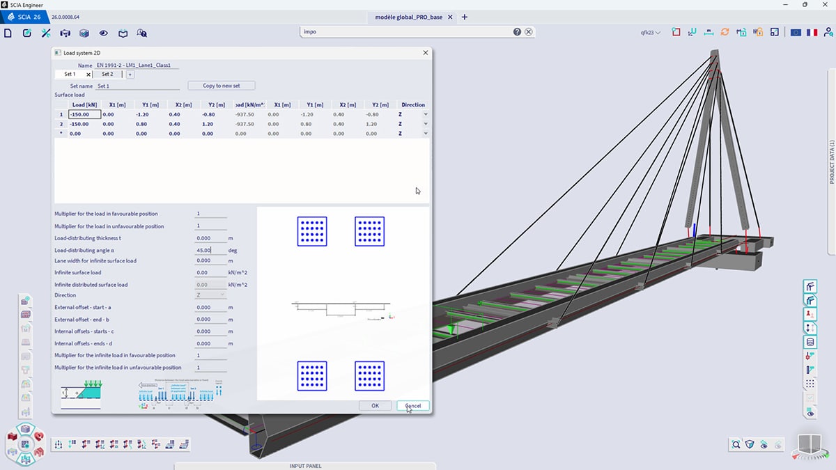
A countersunk corner weld can be automatically selected by AutoWeld and is adjustable, for example, from a certain thickness or in specific situations.
A new functionality within Parabuild is 3D welding. "A traditional hurdle when modeling welds is the amount of drawing work it entails for the draftsman," Joris knows. "To make this a lot faster, we created the AutoWeld engine. Again, the draftsman can define a full set of rules, again without programming. Different weld types and sizes can be automatically assigned by rules based on a wide variety of model information such as sheet thickness, angle, structural types and more. AutoWeld will already automatically draw most structural welds using the standard Parabuild rules. These rules can also be used as the basis for custom rules, which provide welds that follow the habits of one's workshop. Visualization of the welds will help the user determine problematic weld situations and welds with incorrect, often oversized dimensions. All this will ensure shorter welding times on the shop floor and a more economical weld."
Welding symbols are automatically drawn when generating shop drawings. "Parts lists of a project's welds can help estimate welding and schedule welders. The 3D weld objects can also contain manufacturing data and be given a unique number for tracking purposes. In the near future, we plan to expand these capabilities to include support for robotic welding."

As mentioned, the software fully automatically creates DXF and DSTV files for automated drilling, cutting and marking of parts. Automatic scribing is also possible, which eliminates manual measuring and etching/scratching and saves time.
"In recent versions of our software, the functionalities for scribing have been greatly improved," Joris points out. "Contours of welded parts can be added completely, partially or via center points. If the part numbers of those welded parts are desired, the software automatically finds a suitable location for those designations. But we go even further. Since the location of holes is very important, in the latest version a line or point can be added to both the base element and the welded element in line with the holes. So the welder just has to make sure those markings are aligned."
To reduce time losses during production, scribing settings can now be chosen for each situation: for example, working with center points on the main profile and with lines at the corners on plates or placing fewer or no contours on certain types of elements. "There are very many different filters possible, so the user can choose for each unique situation what contours are needed and that is then automatically applied."

Connections are thus not programmed in Parabuild as in classical drawing programs, but defined in template drawings with geometric rules to parametric models. "In this way, a lot of manual modeling work is avoided and you can also make changes afterwards much more efficiently. If the beams change in a parametric connection, the connection automatically goes with it. When detailing steel, it is important to be able to draw very many geometries as quickly as possible. The complexity is not so much in each individual element, but in the amount of elements together that make the overall model complex. This is why Parabuild generates as much as possible automatically, and this also pulls through in the most recently added functionalities, 3D welding and automatic scribing. In the future, we plan to extend this vision of no-code automation further to the other functionalities in Parabuild as well."