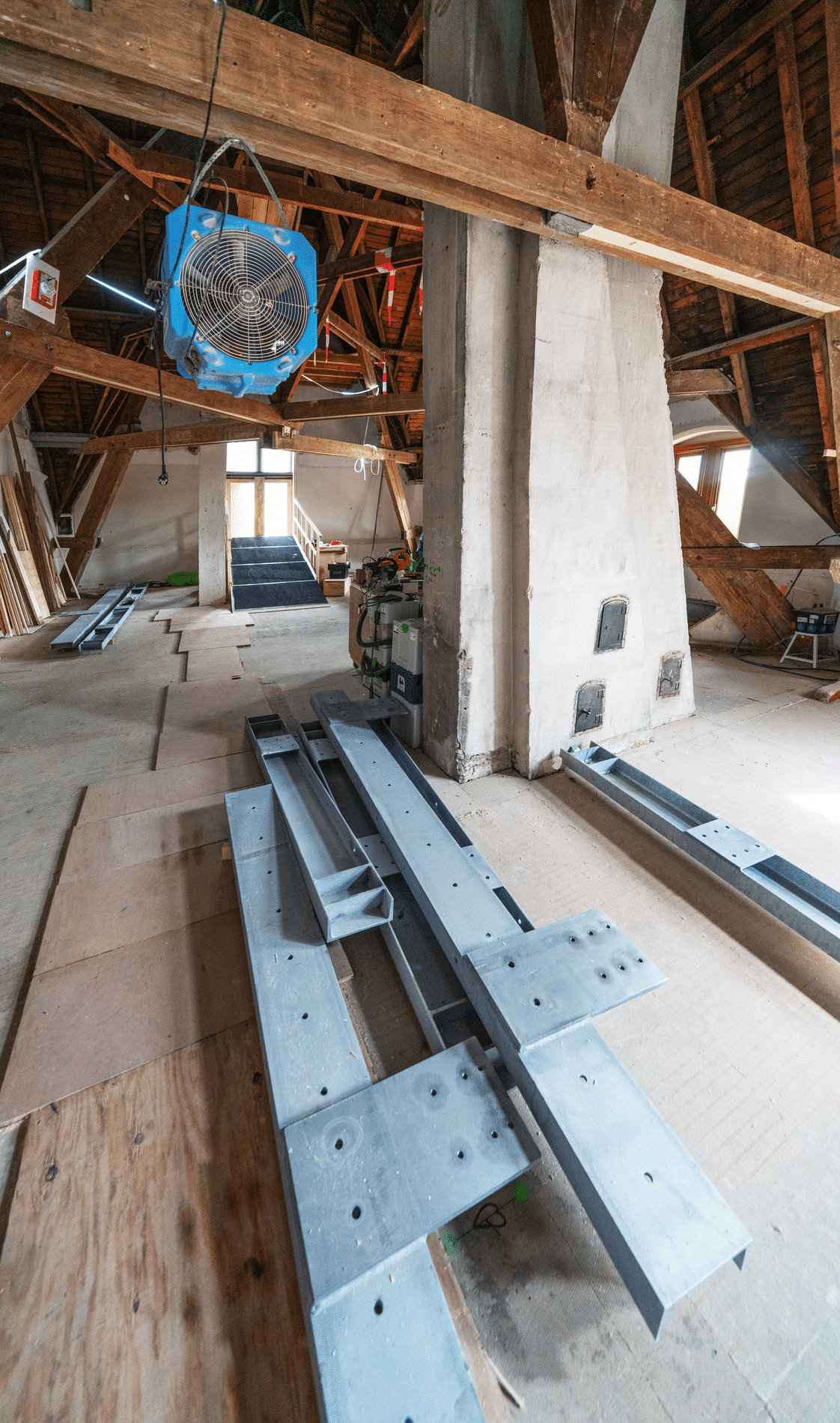
Platform on concrete and steel in construction

The "Cycling through the Trees" project was realized with the help of AVEVA E3D Structural Design and won several national and international awards.

'Cycling through the Trees' in Bosland is a unique cycling experience where you cycle among the trees up to a height of ten meters. On this bike path you can safely reach higher spheres. Literally, because via a double circle you cycle all the way up to ten meters between the treetops. The bike path is 700 meters long in total. You experience nature in a completely different way and become as it were one with the forest. The path is also accessible to walkers and joggers.
The basis of the project is a steel structure. Frederic Sneyers of Smulders (Drawing Office Balen Belgium) talks about the technical challenges of the project, "We were particularly interested in this project because of its complexity.
'First of all the location. It is a forest with small access roads and no amenities such as electricity. In addition, it was a feat of arithmetic. We had to ensure that the soil was disturbed as little as possible, we were also not allowed to use concrete decks to secure the columns. And this is a structure without connections.'
The steel structure is already a bit rusted, was this done for the "looks" of the area?
'There are several reasons for this. The steel used for this is corten steel (weatherproof steel). This has the advantage that the steel does not need any dyeing and has that typical rust color. The architect specifically chose this because the columns are intended to mimic pine trees. And the color of the steel is close to the (natural) color of the tree trunks.
'Because the project is in a forest, we had no storage place to lay columns and floor boards, so we had to load the trailers so that the parts could be assembled directly from the trailer in the right place. Because of this, the project planning also had to be in order. The intention was to keep the nature as pristine as possible and not to grub up everything.'
'This steel needs a different way of treatment than ordinary steel, for example, the pieces all had to be degreased, otherwise this will remain visible after the rusting process. Custom welding wire must also be used for this, and nothing was allowed to be marked on the steel. Handle with care. The bolts used for this also had to be made from Corten steel. Our procurement had to purchase the bolts for this from the US. When mounting the bolts, it is also necessary to use an insulating material so as not to get an interaction between the corten steel and the stainless steel railing.'

'Because we were not allowed to work with a concrete deck to place the columns, we worked with screw piles of ± 2 meters that were put into the ground, on which we could mount a column. In this way, the soil was affected as little as possible. Only the two abutments we had to set on a concrete deck of 5 meters x 5 meters and 2 meters deep. This is because the stability of the structure is absorbed by the two abutments. These two abutments are the anchor for the whole structure, therefore there is no bandage in the whole bridge.
'The crane was placed in the center of the circle, so this had to be a crane that could place ± 7 tons at 50 meters. The suitable crane operators with the right permit are not that plentiful. At the end of the works, this crane also had to get out of the circle, so we took this into account with the assembly order. As a result, we placed some of the columns afterwards. Virtually no greenery was destroyed to carry out these works.
'We first placed an abutment, this had to be set 100% correctly, then the two bridge sections were placed next to each other, only then the intermediate columns until the circle was complete. The last bridge section then closes the circle. This way of working requires a total grip on the correct placement of the columns. If it would deviate only a 0,5°, you cannot connect correctly at the end of the bridge.
the circle. After extensive internal deliberation, we decided to work with special temporary assembly trestles. In this way we could assume that the assembly of the structure would be fast and flawless. The stainless steel handrail was plotted on-site and then professionally welded in the workshop. Only in this way was a perfect fit guaranteed'.
'Working with an architectural firm can also be a challenge to get the visual as beautiful as possible in practice. But again, we successfully completed all the check marks!'
In what ways has AVEVA E3D Structural Design contributed as a drawing package to solving those challenges practically and clearly?
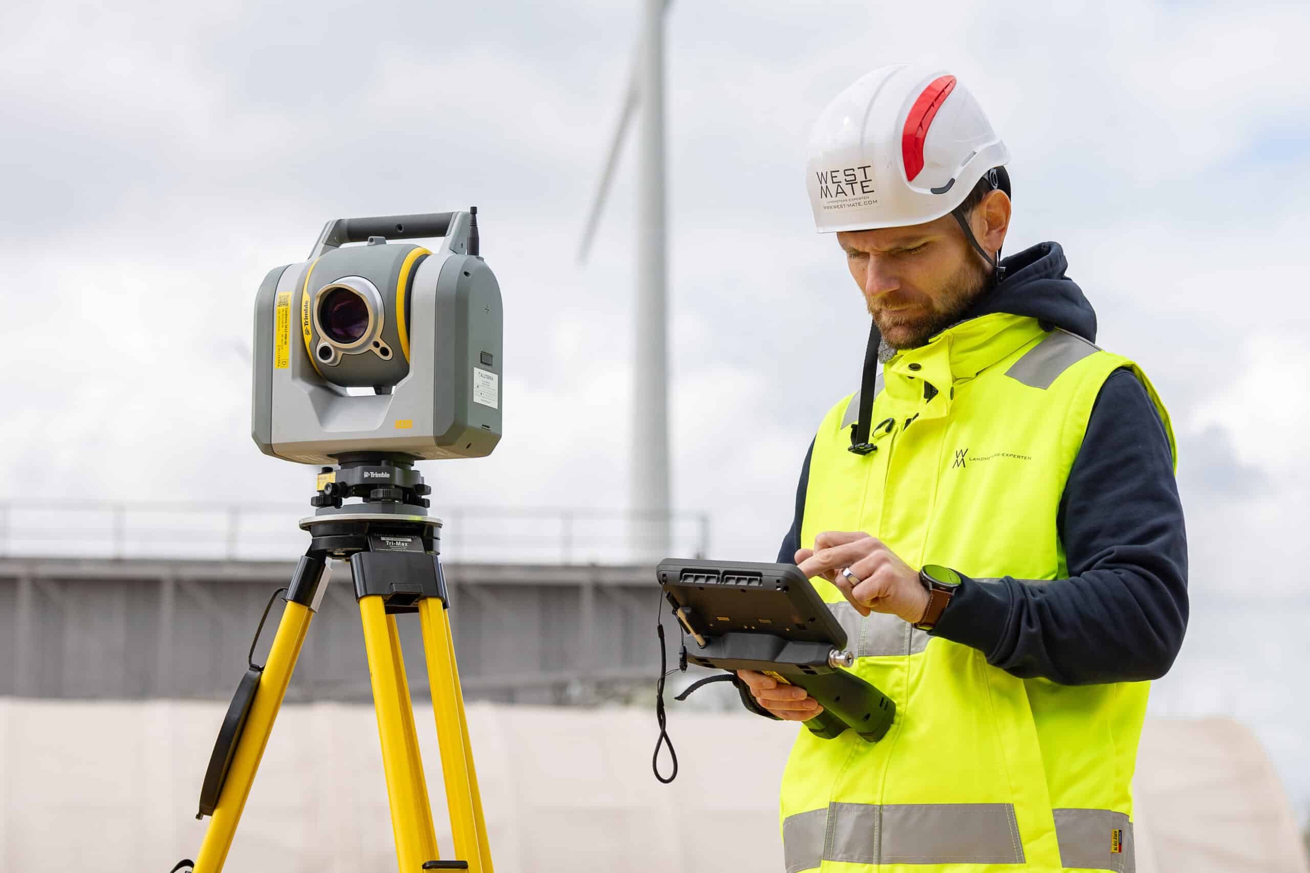
Because it is a curved structure that is also on a slope, AVEVA E3D Structural Design is ideal for drawing this out. The coordinate system was also very useful to determine the exact location of the ground piles, both in x and y direction, but also in z direction (height). The coordinate system was sent to our surveyor by means of an export file. The surveyor plotted each ground stake correctly down to the mm. Afterwards, the ground piles were also set correctly to the mm and this for 449 unique positions.'
How was the conversion from the design to the machines ? Did you do this directly from AVEVA E3D Structural Design ?
'We have an in-house ERP system that controls our machinery, all data comes from AVEVA E3D Structural Design. For example, lists and nc control. This data is processed by our work preparation who then control the machines.'