









Drawing software for efficient steel production
Tekst Roel van GilsFotografie Parabuild
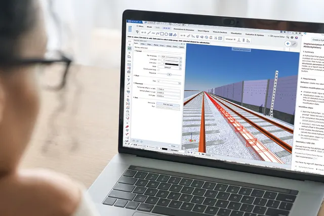
With the intuitive, user-friendly Parabuild drawing software, anyone can quickly and easily draw detailed 3D steel structures, even less experienced draughtspeople. From this 3D model, the software automatically generates high-quality workshop drawings, bills of materials, and DXF and DSTV files for production control. It ensures that greater automation, and the resulting efficiency gains on the shop floor, are not lost in the drawing office. Rudy Joris of Parabuild tells us about two major new features that are making production even more efficient: 3D welding and layout marking.
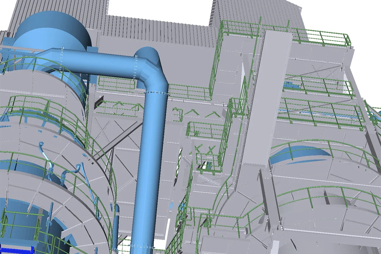
Parametric
Parabuild software is designed to make drawing detailed 3D steel structures as efficient as possible. “It is the only steel construction drawing program that makes it possible to draw steel structures defined entirely by geometric rules,” says Joris. “Connections and macros defined in template drawings can be reused in any project to automate repetitive work. The same applies to entire structures, trusses, bracing, cladding, stairs, and more. This means Parabuild can be customised without hiring a programmer or writing complicated code.”
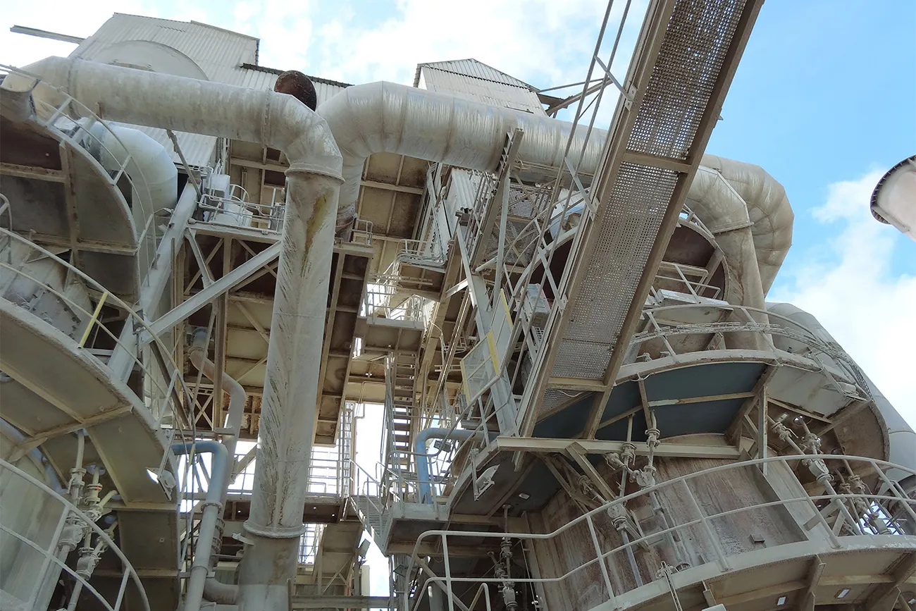
Parabuild has a library of hundreds of standard steel construction connections. “Drawing connections is a matter of selecting the steel sections, and the software will suggest only the valid types for that situation,” Joris explains. “The connection is drawn immediately, and any changes are shown straight away on the 3D model. Drawing a fully detailed steel structure has never been easier.”
Workshop drawings and CNC
The 3D model of the steel structure is used as the basis for automatically generating workshop drawings, bills of materials, and CNC and IFC files. General arrangement drawings, approval drawings and more are easy to create and linked to the 3D model. Dimensions and labels are automatically added to workshop drawings, while advanced optimisation algorithms ensure clear, legible layouts. This automation produces accurate drawings and prevents errors.
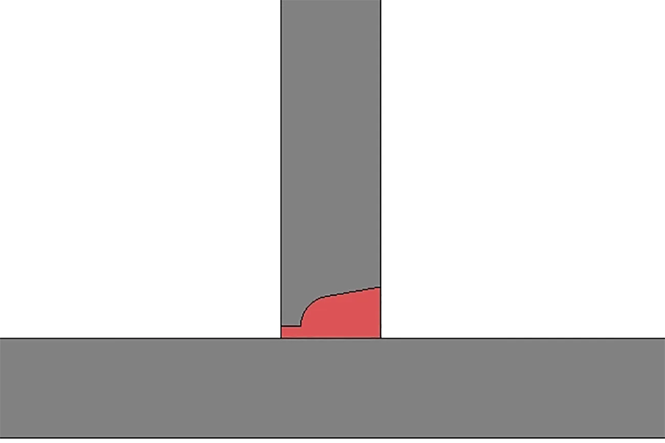
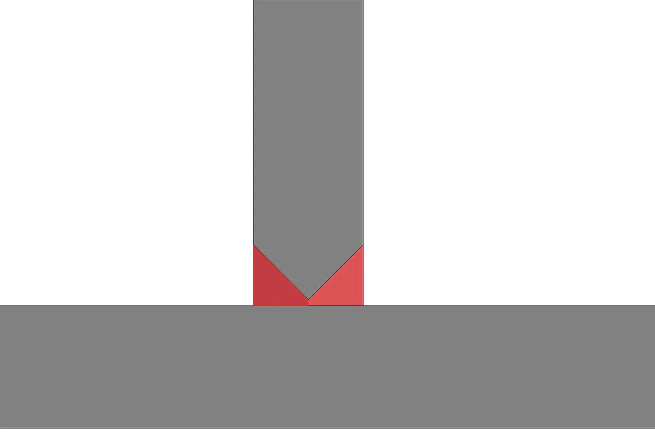
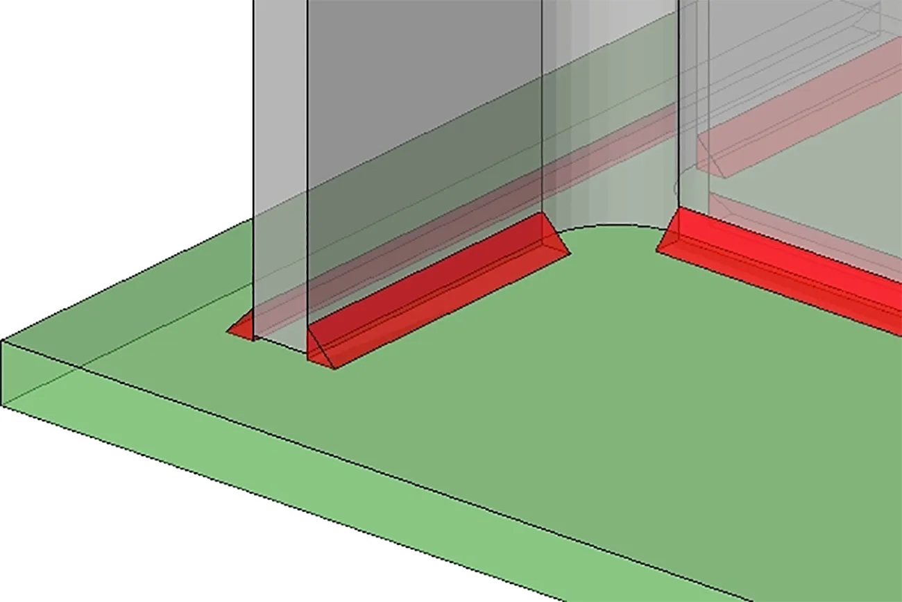
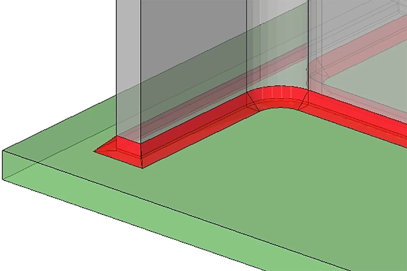
AutoWeld can automatically select a recessed fillet weld, which can be configured, for example, to apply above a certain thickness or in specific situations.
3D welding
A new feature in Parabuild is 3D welding. “One traditional obstacle to modelling welds is the amount of drawing work it entails for the draughtsperson,” says Joris. “To speed this up considerably, we created the AutoWeld engine. Here too, the draughtsperson can define a complete set of rules without any programming. Different weld types and sizes can be assigned automatically using rules based on a wide range of model information, such as plate thickness, angle, structural types and much more. Using the standard Parabuild rules, AutoWeld will already draw most structural welds automatically. These rules can also serve as a basis for custom rules that ensure welds follow the practices of the individual workshop. Visualising the welds helps users identify problematic welding situations and welds with incorrect, often excessive, sizes. All this means shorter welding times on the shop floor and more economical use of weld material.”
Weld symbols are automatically added when workshop drawings are generated. “Bills of materials for a project’s welds can help estimate the welding work and schedule welders. The 3D weld objects can also contain fabrication data and be assigned a unique number for tracking purposes. In the near future, we want to expand these capabilities to include support for robotic welding.”
Automatic layout marking
As mentioned, the software automatically creates DXF and DSTV files for automated drilling, sawing and marking of parts. Automatic scribing is also possible, eliminating manual measuring and etching/scratching, and saving time.
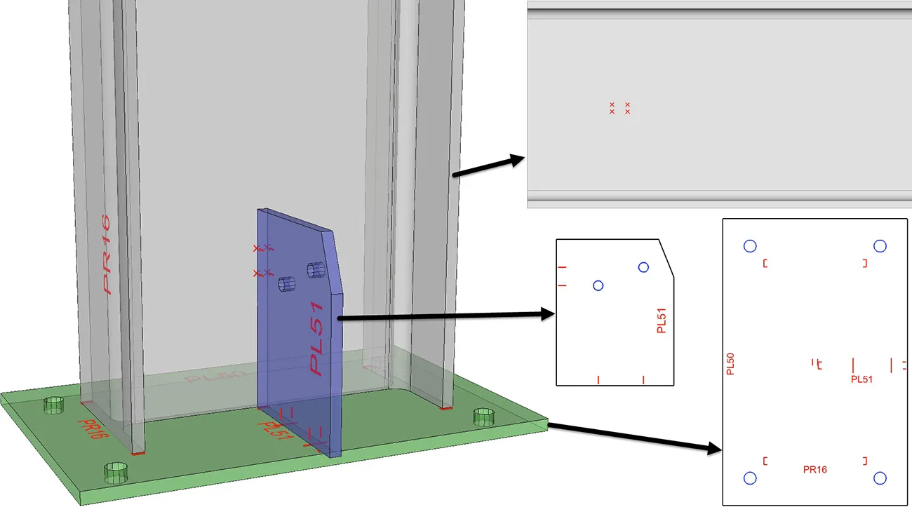
“In recent versions of our software, the scribing features have been greatly improved,” says Joris. “Contours of welded parts can be added in full, in part or using centre points. If part numbers for those welded parts are required, the software automatically finds a suitable location for the labels. But we go further still. Since the location of holes is very important, the latest version can add a line or point on both the base element and the attached element, extending along the line of the holes. This means the welder only has to make sure those marks are aligned.”
To reduce production delays, users can now choose scribing settings for every situation: for example, using centre points on the main section and lines at the corners of plates, or adding fewer or no contours for certain types of elements. “There are many different filters, allowing users to choose which contours are needed for each individual situation, and this is then applied automatically.”
No-code
Connections in Parabuild are not programmed as they are in conventional drawing programs. Instead, they are defined in template drawings using geometric rules to create parametric models. “This avoids a lot of manual modelling work and makes it much more efficient to implement changes later on. If the beams change in a parametric connection, the connection adjusts automatically. When detailing steel, it is important to be able to draw a large number of geometries as quickly as possible. The complexity lies not so much in each individual element, but in the number of elements together that makes the overall model complex. That is why Parabuild automates as much as possible, and this approach also extends to the most recently added features: 3D welding and automatic scribing. In the future, we plan to extend this no-code automation approach to other Parabuild features as well.”
Een zakelijke vraag aan Parabuild? Neem contact op
Bedrijven in dit verhaal
Blijf dit volgen
Bij een nieuw verhaal krijg je een e-mail. Geen account nodig.
- OnderwerpSoftware & automation
- BedrijfParabuild